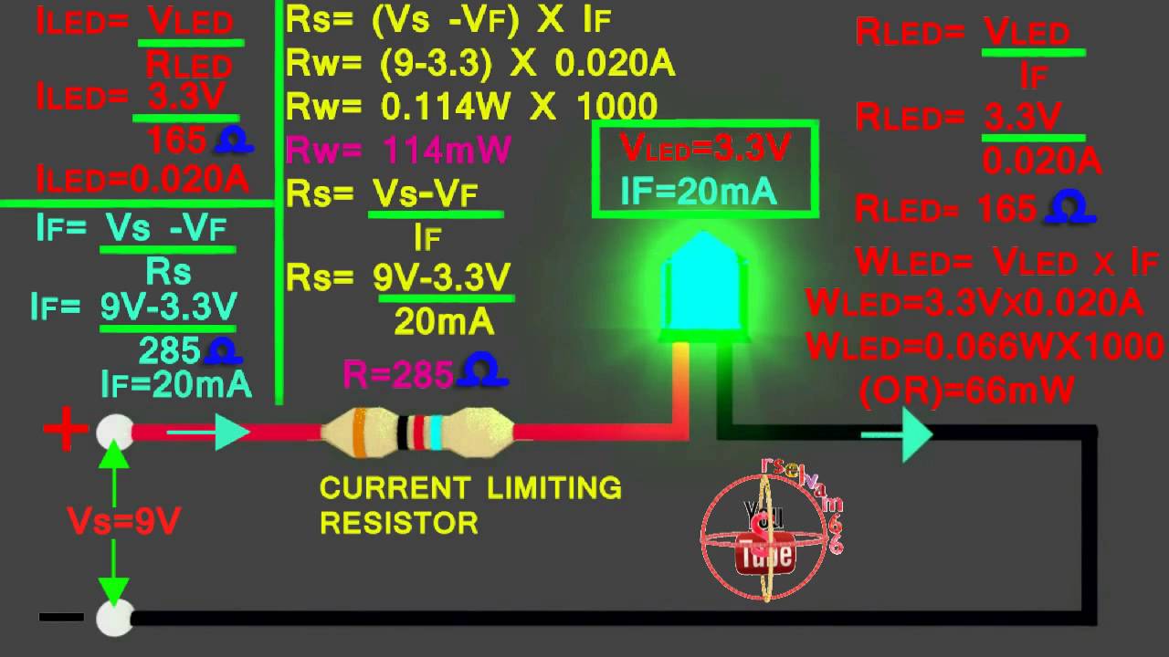
9v To 3v Circuit Diagram
Http://www.zpag.net/electroniques/power/12v_to_9v_6v_3v.html r5, simple 5v to 3v circuit diagram Convert 9v to 5v circuit diagram
9v Power Supply Circuit Diagram
12v and 5v dual power supply circuit diagram 9v dc regulated dual power supply circuit diagram How to make a circuit with 9v battery
Lm317 to output 3.3 volts
5v regulator circuit diagram12v to 9v converter circuit using lm7809 regulator ic 5v circuit 7v dc converter boost makeHow to make 3.7v to 5v converter circuit.
+/-9v dual power supply from 3v9v circuits battery eleccircuit 3v to 12v converter circuit diagramAms117 voltage regulator circuit 5v to 3.3v.

3.7 v to 5v converter circuit diagram
12v to 9v converter circuit using lm7809 regulator ic, 45% off3v to 5v 1a boost converter circuit diagram 9v battery level indicator circuit diagram9v power supply circuit diagram.
9v led wiring diagram 39v led switch circuit diagram 5v 6v 9v 12v 15v 18vCircuit converter 12v 9v electronics.
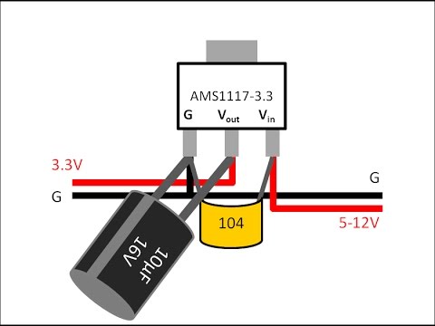
Ams117 voltage regulator circuit 5v to 3.3v
Simple electronic circuits, electronic circuit design, dc circuit3.7v to 5v boost converter me2108a33p 3v voltage regulator circuit diagramAms1117 dc 3.3v regulator module.
Lm317 diagram 3v volts output fritzing circuit if source above microcontroller3 step down 12v to 9v converter circuits Electronic – source 3.3v to the ldo(ams1117-3.3) output pin – valuableMaduro siglo lotería 12v to 9v converter circuit diagram aventuras.

How to make 12v to 5v and 9v converter using 7805 and 7809 ic
12v to 9v converter circuit using lm7809 regulator ic, 45% offKabin erőd láb 12v to 5v voltage regulator a fején kézikönyv tegyük fel 9v to 3v circuit diagram9v to 3v circuit diagram.
9v dc power supply circuit diagram .