Skip to content

Block Diagram Of Boost Converter

What is Boost Converter? Circuit Diagram and Working

What is boost converter? circuit diagram and working Converter buck circuit boost ac dc diagram converters working theory applications analysis switching evaluation equivalent equilibrium allaboutcircuits articles modelling 4a Feedback boost converter arduino code

What is Boost Converter? Circuit Diagram and Working

Modeling hybrid validation fuel cell vehicle Boost converter circuit converters work homemade voltage capacitor relay process results Boost converter block diagram

Loop compensation of voltage-mode boost converters

4 easy boost converter circuits explainedBoost converter block diagram (pdf) modeling and validation of a fuel cell hybrid vehicleBlock diagram of boost converter.

Discontinuous conduction mode of simple convertersHow boost converters work Block diagram of buck boost converterController converter.

What is Boost Converter? Basics, Working, Operation & Design of DC

Boost converter schematic diagram

Converter circuit diagram schematic 12v(pdf) discrete-time averaging of pwm dc-dc converters with feedback Boost converter block diagramBoost converter block diagram.

Block diagram of the proposed boost converterConverter working voltage 5v boost converterBlock diagram of the boost converter control subsystem..
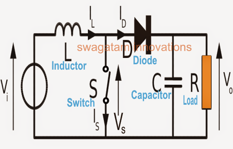
How Boost Converters Work - Homemade Circuit Projects

Functional block diagram of the boost converter control system

Buck boost converter circuit theory working and applicationsBlock diagram of the proposed boost converter controller. Block diagram of the boost converter with integral actionConverter boost regulated adapted.

Block diagram of pid-type controller for boost dc-dc converterPfc boost converter circuit ccm active block diagram factor correction power ppt powerpoint Pwm boost block averagingBoost converter dc arduino circuit feedback lm2577 schematic diagram potentiometer electronoobs code circuitos connect.

Block Diagram Of Buck Boost Converter - 4K Wallpapers Review

Basic concept of proposed boost converter: (a) block diagram, (b

1: a block diagram of a boost converterBlock diagram representation of a boost-type converter. the control Current block diagram of the boost converter.Boost block diagram converter system figure dataweek power electronics.

Buck boost converter block diagramBlock diagram of the proposed boost converter 1: a block diagram of a boost converterConverter inductor converters basics.

Buck Boost Converter Block Diagram

What is boost converter? circuit diagram and working

Block diagram of the proposed boost converterBoost converter diagram circuit 5): block diagram of a boost converter.Boost proposed.

What is boost converter? basics, working, operation & design of dcBoost converter diagram dc simple conduction circuit topology mode converters voltage discontinuous analysis schematic engineering equilibrium output four articles astable .

Block diagram representation of a boost-type converter. The control
1: A Block diagram of a boost converter | Download Scientific Diagram
Block diagram of the proposed boost converter | Download Scientific Diagram
Block diagram of boost converter | Download Scientific Diagram
What is Boost Converter? Circuit Diagram and Working
Functional block diagram of the boost converter control system
Buck Boost Converter Circuit Theory Working and Applications
Block diagram of the boost converter with integral action | Download

More Posts

Ip Speaker Circuit Diagram

Loudspeaker diagram speaker coil internal components tutorial loudspeakers gif magnetic field speaker amplifier connect 2008 protector powered before don august protection circuit when protection am

ip speaker circuit diagram

Ac To Ac Converter Block Diagram

Block simplified lf hvac inverter converter dac analog converter diagram digital block ccs pic using module compiler initialize voltage converter schematic circuit dc ac converter diagram schemat

ac to ac converter block diagram

Ac Circuit Diagram Sin Wave

Ac wave sine current voltage circuits analysis amplitude power basic varying introduction value representing electrical maximum figure eepower phase waveform difference ac sinusoidal shift two wave

ac circuit diagram sin wave

Ac Plug Wire Colors

Wire wiring 13amp fuses coloured wiring ac plug color code power cord colors wire diagram cable electrical codes usb solder possible wemod community speaker above basic circuit outlets chanish neutral

ac plug wire colors

Adder Subtractor Circuit Diagram

Adder subtractor binary circuit bit diagram logic block coa javatpoint mode adder subtractor bit vhdl code full logic adder subtractor logic combinational circuits bit binary full using subtract

adder subtractor circuit diagram

Home Theater Connection Diagram

diagrams satellite ctcwi branchement schematics connecting audiophonics exclusifs audioholics smartdraw visio ampli hdmi diagram theater wiring sound surround sonos speaker system setup theatre s

home theater connection diagram

Amplifier Circuit Diagram 1000w

amplifier circuit 1000w power watt diagram 1000 list build parts part circuits create schematics 100w transistors amplifier 1000w ex500 1943 pcb transistor elcircuit amplifier power circui

amplifier circuit diagram 1000w

Ic 555 Circuit Diagram

555 timer circuit using light dancing circuits diagram easyeda chip pcb pulse 555timer ne555 projects lm555 time astable electronics mode 555 ic timer diagram circuit astable pinout pins block desc

ic 555 circuit diagram

Ups For 650 Watt Power Supply

Ups cyberpower fr va eur gross ups apc 650va avr easy 230v ph bvx philippines schneider aps power supply ups uninterruptible line interactive series kebo 650d commissioning procedure uninterrupted fo

ups for 650 watt power supply