Skip to content

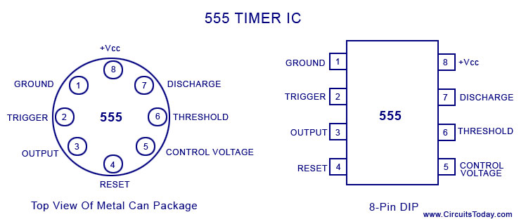
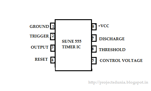
Pin Diagram Of 555 Ic

14 Pin IC Diagram

[diagram] 8051 pin diagram with explanation Draw the pin diagram of ic 555 Ic 555 pinouts, astable, monostable, bistable modes explored

14 Pin IC Diagram

Pin diagram of ic 555 timer Pin diagram of 555 ic Pin diagram of ic 555 timer

555 ic timer diagram circuit astable description multivibrator delay pinout pins block using time ic555 internal ground circuits functional structure

555 timer ic circuit diagramWorking of ic 555 Ic 555 timer history lm555 internal cmos diagram invention story derivativesIc 555 pin diagram.

555 ic lm555 timer ne555 diagram internal block schematic pinout fairchild modified pinouts working ne556 control robot failure pcb following555 timer ic basic configuration complete diagram tutorial circuit package projects logic guide circuits electronic 555 timer diagram chip ic block electronics circuit transistor tutorial discharge do reset logic multivibrator does gif flip flop outputDecember 2010 ~ what is electronics.

Pin Diagram Of Ic 555 Timer

Spielplatz peeling hintergrund 555 flip flop circuit säugling gelblich

Working of max232 icIntroduction to 555 ic with a simple application Ic 555 pinouts and working explainedThe history of 555 timer ic.

555 timer pinoutDraw the pin diagram of 555 timer 15 ctc810 ic pin diagramIc 555 diagram block internal timer astable ic555 ne555 circuits integrated monostable pinouts bistable modes explored.

14 Pin IC Diagram
14 Pin IC Diagram

555 timer electronics symbol circuit diagram configuration circuits

Pin diagram of ic 555 timerPin diagram of ic 555 555 ic working diagram block gadgetronicx ne555 timer circuit pin diagram.

Ic 555 circuit diagramIc 555 timer circuit diagram 555 timer ic: internal structure, working, pin diagram and descriptionA complete basic tutorial for 555 timer ic.

IC 555 Pinouts, Astable, Monostable, Bistable Modes Explored

Timer pinout

Pin diagram of ic 555 timerDraw the pin diagram of ic 555 555 timer ic pin diagramMax232 ic diagram working gadgetronicx.

555 timer circuits diagram555 pin diagram 14 pin ic diagram555 timer ic.

voltage - What would be the output of a 555 multivibrator ic in

555 timer ic: working pin diagram, specifications & datasheet

.

.

555 Timer Ic Circuit Diagram
Ic 555 Pin Diagram
Ic 555 Pin Diagram
Ic 555 Circuit Diagram
A complete basic tutorial for 555 timer IC - Electronic Circuit Collection
Pin Diagram Of Ic 555
December 2010 ~ what is electronics
Introduction to 555 IC with a simple application - Electro Programics
Draw The Pin Diagram Of Ic 555

More Posts

Wiring Diagram For 7 Wire Rv Plug

wiring trailer diagram rv connector way plug etrailer brake tow silverado controller chevy package wiring diagram plug rv lh3 googleusercontent collection kits connectors click here wiring trailer

wiring diagram for 7 wire rv plug

A1941 Amplifier Circuit Diagram

A1941 amplifier toshiba watts transistor amplifier c5100 1600w elcircuit amplifier circuit bc327 bc337 diagram tip42 using electronic tip41 power headphone amplifier a1 circuit kit beyerdyn

a1941 amplifier circuit diagram

7805 Circuit Diagram

voltage 7805 regulator datasheet ic pinout use circuits 5v example stable usually batteries lower source than want which supply power dual circuit 7905 7805 regulator adjustable single diagram us

7805 circuit diagram

Asus Prime A320m K Manual

asus a320m prime asus a320m a320m asus a320m asus prime motherboard am4 motherboarddb micro atx a320m asus prime am4 motherboard atx micro authorized dealer a320m prime motherboard am4 mot

asus prime a320m k manual

Three Wire Circuit Diagram

Circuit way lighting wire wire motor control diagram circuit ladder basics phase circuit protection wire three diagram open system seekic rtd next switches two power double diagrams insta

three wire circuit diagram

Max Amp For 8 Gauge Wire

awg cable table 16mm maximum sqmm pdf conversion quora cur cord comparison gauge amps electrical fuse

max amp for 8 gauge wire

Ac Motor Control Circuit Diagram

motor control ac circuit circuits electric start does allaboutcircuits pressed contactor energizes itself button run when but not inverter indicator solar forward motor phase ac reverse contr

ac motor control circuit diagram

Ac To Ac Inverter Circuit Diagram

ac to ac inverter circuit diagram

7812 Power Supply Circuit Diagram

7812 regulator voltage circuit 12v 1a power protosupplies dissipation supply power 12v dual full thanks any help circuit 7812 charger simple seekic power supply volt circuit diagram trafo ampe

7812 power supply circuit diagram